Input register to 0. Input Register 8 bits OUTR.

Build Your Own 6502 Microprocessor Kit Tact Switch Shift Register Microcontrollers
Input flag 1 and the processor transfer data of INPR to AC and change FGI.
. Modern CPU architectures tends to use more GPR so that register-to-register addressing can be used more which is comparatively faster than other addressing modes. Current Instruction Register CIR - this holds the current instruction being executed. When there are 4 jobs the CPU is round-robin among the four as is the IO.
The program counter gives an address value in the memory of where the. Input Flag 1 bit FGO. Input Flag 1 bit.
The following registers are contained in the processor and connected directly to the system bus. Input register 8 bits OUTR. When effective access time is 15 ns.
The following registers are contained in the CPU and connected directly to the systembus. A the address of the Interrupt Service Routine ISR is loaded to the Program Counter PC. First stage of the instruction cycle.
Which points to the next memory line where the next processor instruction is located. These are numbered as R0 R1 R2Rn-1 and used to store temporary data during any ongoing operation. Input Register 8 bits.
Program Counter or Program Counter. Output Register 8 bits FGI. Output flag 1 bit IEN.
The registers are the most easily accessible memory location for the CPU and sit on the top of the memory hierarchy. Input Flag 1 bit. Interrupt Enable 1 bit Keystroke input from the Teletype and output to the printer are controlled by the IO module.
General Purpose Registers. The following registers are contained in the processor and connected directly to the system bus. Describe how the.
Output Flag 1 bit IEN. They are much smaller than local memory and are used to store machine instructions memory addresses and certain other values. When there are 4 jobs the CPU is round-robin among the four as is the IO.
Register are used to quickly accept store and transfer data and instructions that are being used immediately by the CPU there are various types of Registers those are used for various purpose. Among of the some Mostly used Registers named as AC or Accumulator Data Register or DR the AR or Address Register program counter PC. Output Register 8 bits FGI.
It can be read only or write only write once and reset to clear data write many read to clear write to clear and protected in the system. The following registers are contained in the processor and con-nected directly to the system bus. Interrupt enable 1 bit Keystroke input from the teletype and printer.
The following registers are contained in the CPU and connected directlyto the system bus. Describe how the processor using the first four registers listed in the problem can achieve IO with the teletype. The registers you should know about include.
The first stage of the instruction cycle is responsible for capturing the instructions in the RAM memory assigned to the processor through a series of units and registers that are the following. The hit ratio needed to register the level is 096. Input register 8 bits.
Output flag 1 bit. The general purpose registers GPR are used in CPU architecture for either storing the data memory addresses or instructions. Interrupt Enable 1 bit Keystroke input from the teletype.
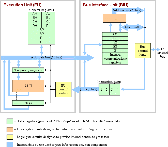
The Intel 8088 CPU. 1 describe how the cpu when using the first 4. Keystroke input from the teletype and printer output to the teletype are controlled by the IO module.
This preview shows page 9 - 10 out of 10 pages. Output Flag 1 bit IEN. Input Register 8 bits OUTR.
The general purpose registers are named registers R1 R2 R3. Consider a computer system that contains an IO module controlling a simple key-boardprinter teletype. Output register 8 bits.
It stores the address of memory where CPU wants to read or write data. Interrupt Enable 1 bit Keystroke input from the teletype and printer output to the teletype are controlled by the IO module. This register stores the contents of data or instruction read from or written in the memory.
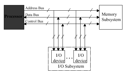
The following registers are contained in the processor and connected directly to the system bus. Consider a computer systemthat contains an IO module controlling a simple keyboardprinter teletype. The teletype is able to encode an alphanumeric symbol to an 8-bit word and decode an 8-bit word into an alphanumeric symbol.
Interrupt enable 1 bit. Input flag 1 bit. Data is loaded from the main memory to the registers via the CPU cache after which it undergoes.
Consider a computer system that contains an IO module controlling a simple keyboardprinter Teletype. Registers are classified based on their functionality and behavior. Consider a computer system that contains an IO module controlling a simple keyboard printer teletype.
The following registers are contained in the CPU and connected directly to the system bus. Output Register 8 bits. And once 8-bit data enters the INPR then FGI.
RAM is a temporal storage area in the computer system that usually contains the data that are being processed by the CPU. The User-visible register and the Control status registers. In short this register is used to store datainstruction coming from the memory or going to the memory.
HrTr 1-HrHcTc 1-Hr 1-HcTm 09210 1-09209590 1-092 1-0951000 92 684 4 2004 ns Answer 2. Input Register 8 bits OUTR. The processor checks the program counter to see which instruction to run next.
IO CPU IO CPU Job2. The general roles performed by processor registers are mainly from two registers. Program Counter PC - this holds the address of the next instruction to be fetched and executed.
Output Register 8 bits. Briefly describe how the CPU and the RAM interacts to carry out their operation. Input Flag 1 bit FGO.
The processor contains number of general purpose registers. Consider a computer system that contains an IO module controlling a simple keyboardprinter teletype. Output Flag 1 bit.
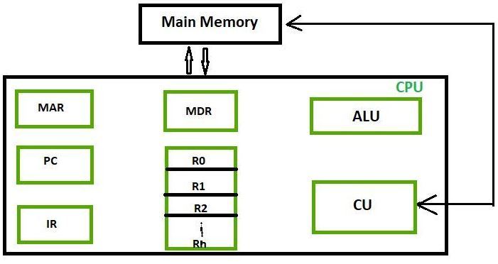
The memory locations are accessed by its address. Memory Address Register MAR - this holds the RAM address you want to read to or write from. Components of Register in Microprocessor.
Its content can be accessed by assembly programming. Input flag 1 bit FGO. Output Flag 1 bit IEN.
Input flag 0 it will be accepted by INPR. Processor Utilization 100 IO first and fourth quarters processor second and third quarter The answers for this part are the same as the first. Output Register 8 bits FGI.
Based on these functionalities the registers are selected in the system to work for specific purposes in the processor. This is easy to see for the case of 1 job and 2 jobs. I CP O I CP O.
Input Flag 1 bit. Input Flag 1 bit FGO. The following registers are contained in the CPU and connected directly to the system bus.
Interrupt Enable 1 bit. The following registers are contained in the processor and connected directly to the system bus. This means the jobs are interleaved as.
Output register 8 bits FGI.
Different Classes Of Cpu Registers Geeksforgeeks
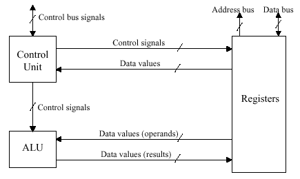
Organization Of Computer Systems Processor Datapath
Organization Of Computer Systems Processor Datapath
Introduction To Microprocessors


0 Comments